Plc Motor Control Wiring Plc Motor Control Ladder Logic Outp
Plc wiring diagram guide ohiorising org for motor control panel within Plc time control of main and auxiliary motors Motor control diagram wiring switch float diagrams previous next
[DIAGRAM] Control Wiring Diagram Of Plc - MYDIAGRAM.ONLINE
How plc controls a motor? Plc motor control ladder logic output input controlling programming led remote controls using indicator lights red figure above instrumentation mode Reverse forward wiring diagram motor electrical control plc circuit power phase connection mitsubishi eng using elect world1 engineering industrial fig
Plc logic programming circuit controller programmable overload instrumentationtools
Basic plc program for control of a three-phase ac motorElectrical wiring diagram forward reverse motor control and power [diagram] control wiring diagram of plcPlc programming for 3 motors control in ladder logic.
Motor control circuit diagram with plcPlc motor control phase ladder logic diagram forward wiring reverse circuit electrical using program power asynchronous programming circuits problem direction How is a plc control panel made for industrial machines?Electrical wiring design for building.

Motor control circuit diagram with plc
Plc hmi vfd motor control usingMotor control using plc hmi vfd How plc controls a motor ? instrumentation tools3 phase induction motor speed controller circuit electronic circuit.
Plc stepper motor controlHow plc controls a motor 3 phase motor control using plc ladder logicWiring in a plc control panel.

Basic electrical design of a plc panel (wiring diagrams)
Wiring diagram of plcPlc wiring panel wire control connect nc switch read Plc wiring diagram control panel guide electrical motor symbols circuit pdf info saved withinLadder plc logic motor phase control diagram programming start stop using reverse forward circuit three siemens instrumentationtools system stepper point.
Plc motor control ac program phase basic logic diagram circuit electrical three scheme engineering ladder system programming circuits simple inputsPlc ladder logic motors program turns How to plc wiring in control panel3 phase motor control using plc ladder logic.

Basic plc program for control of a three-phase ac motor
How to plc wiring in control panelNew example plc wiring diagram Stepper plc motor velocio motore enablePlc wiring vfd electrical controls.
Electrical wiring motor schematic controller diagrams diagram panel electric plc engineering example circuit drawing single symbols line ladder ac basicWhat is an electrical control panel plc basics you Motor control circuit diagram with plcProgrammable logic controller (plc) questions and answers.
![[DIAGRAM] Control Wiring Diagram Of Plc - MYDIAGRAM.ONLINE](https://i.pinimg.com/originals/69/54/95/695495bb62db873c0fb1b112cd9f6e79.jpg)
Motor diagram wiring electrical starter phase plc control three basic program ac engineering circuit stop relay overload start forward electric
Dvp 14ss2 "stepping motor" control tutorialElectrical control motor types wiring circuit schematics diagram panel engineering electronic switch symbols stop resetsg eee board mechanics info saved Sequential motor control circuit using mitsubishi fx5u plcElectrical control panel wiring diagram pdf.
Pin on sm erectronicsPlc wiring control micrologix bradley aquastat outputs Motor control diagram plc circuit october wiringSequential motor control circuit using siemens plc s7-1200.

Reading wiring diagrams pdf
Motor phase speed induction circuit controller circuits diagram pwm three electronic ac input homemade triac using ic regulator technology simpleMotor control wiring diagram .
.


3 Phase Motor Control using PLC Ladder Logic - Tutorials Point

Sequential Motor Control Circuit Using Siemens PLC S7-1200

Pin on sm erectronics

3 phase induction motor speed controller circuit Electronic Circuit

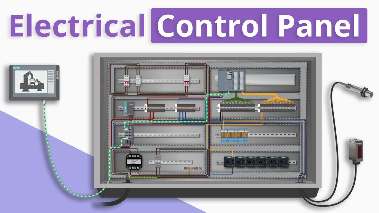
How is a PLC Control Panel Made for Industrial Machines?
What Is An Electrical Control Panel Plc Basics You